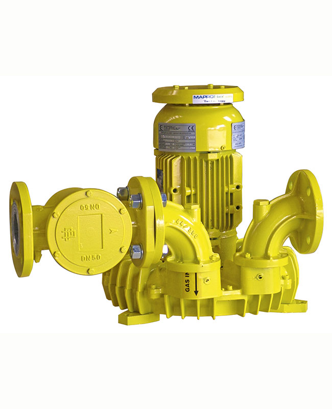
Side channel biogas blowers CL series

Single stage or double stage side channel blowers, construction in aluminium alloy, close coupled to electric motor, ΑΤΕΧ certified, 2G or 3G, for zone 1 or 2. Optionally provided with special suction filter and by-pass valve.
- Pressure up to 550 mbar (g)
- Vacuum up to 450 mbar (a)
- Flowrate up to 1,100 m³/h
Principle of operation
The side channel blower or exhauster increases the pressure of the aspirated gas by the creation, in the peripheral toroidal channel, of a series of vortexes caused by the centrifugal thrust of the impeller. While the impeller is rotating, the vanes force the gas forward and, because of the centrifugal thrust, outwards, producing a helical motion. During this motion, the gas is recompressed repeatedly with a consequent linear pressure increase along the length of the channel.

Generalities and construction features in conformity with the 2014/34/EU Directive (ATEX)
The MAPRO® side channel blowers to be used for extraction or compression of combustible gases, such as biological or natural gas, have been designed in order to fall within the Equipment- Group II as required by the 2014/34/EU Directive, Category 2 both for the surrounding area conditions and for the internals of the machines.
Main construction features:
- Casing and impellers made completely of spark proof aluminium alloy
- Casing impregnated with Loctite
- Casing halves sealed
- Shaft sealing by special double-lip seals which do not require lubrication
- Two-pole, type of protection “d”, flameproof electric motors, with specific marking Ex II 2 G, additional marking Ex-d IIB T3
The simplest solution for the manufacturing of the machines is the so-called “CLOSE COUPLED” version – i.e., a flange mounted electric motor is bolted to the blower casing; the impeller, which is dynamically balanced, is fitted directly onto the motor shaft extension.
Machines with gas recirculation (by-pass)
When the gas pressure increase is low and a variable gas flow is required (as for a burner feeding), a “compact by-pass”, directly bolted to the machine and connecting outlet and inlet ports, is a simple and effective solution. A suitable overpressure relief valve is fitted inside the “compact by-pass”.
When the gas demand decreases, the outlet pressure increases, and, when the set pressure is reached, the overpressure relief valve starts to open and by-passes excess gas back to the blower suction.
Usually the “compact by-pass” is capable of handling the full capacity of the blower for a maximum of 5 minutes. So, during this period the machine can continue to run even if the downstream gas demand is reduced to zero.
For higher differential pressures, where the use of a “compact by-pass” is not allowed because of the high temperature increase when the flow rate is by-passed back to the suction, the machine can be supplied with the overpressure relief valve fitted on an offtake at the outlet side.
In that case the flanged valve discharge shall be piped-back to the blower suction through a by-pass pipe long enough to allow for sufficient gas cooling.
On request, we can supply machines equipped with a suitable gas cooler at the blower outlet, with overpressure relief valve fitted in an offtake at the cooler outlet, and with the complete “by-pass pipe” back to the blower suction side.
We can also supply automatic flow rate adjustment by means of pneumatic or electrically operated flow control valve, fitted in the by-pass line and controlled via the client process parameter “discharge gas pressure”.

Machines controlled via frequency inverter
If the gas demand varies in time (such as for burner or engine feeding), we can supply blowers equipped with a motor intended for control via frequency inverter. The rpm range of the blower (and therefore the output frequency range of the frequency inverter) can be adjusted according to the foreseen operating conditions, and in particular to the expected differential pressure between blower discharge and suction.
The speed of rotation of the motor shall be controlled via the “discharge gas pressure” process parameter.
Complete range of accessories:
- Gas-tight filters
- Stainless steel flanged flexible connection bellows
- Non return valves
- Pressure gauges and thermometers
- Explosion-proof pressure switches and temperature switches
- Intrinsically-safe pressure and temperature transducers
- Manual and automatic cut-off valves
- Acoustic enclosures


