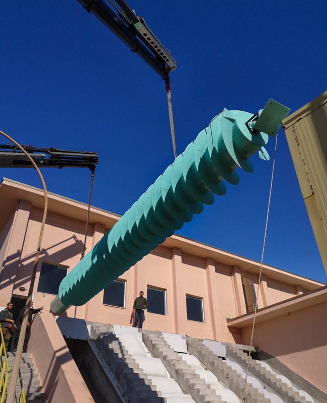
Archimedean screw pumps

The (Archimedean) Screw Pumps are well-known for their excellent qualities such as the Simple & Rugged design, the high efficiency, the capacity to pump raw water (even when it contains an amount of solids and debris) and their lifetime reliability.
Spaans Babcock has a worldwide reputation of being the oldest and the largest manufacturer of Archimedean Screw Pumps with a track-record of more than 30,000 screw pumps installed.
Screw Pumps can be used for capacities from 15 litres/sec up to max 11 m3/sec and come in 3 basic forms: built in the traditional concrete trough, with steel trough liner and the prefabricated, ‘ready to install’ compact units.
The most common application is in waste water treatment plants for lifting the incoming sewage to a higher level without the need of installing a screen upstream and to pump back to the same level the return sludge.
Screw Pump in a Concrete Trough
The classic and most common form is the arrangement of the screw pump in an open concrete trough where the screw, suspended between the upper- and lower bearing, rotates free from the trough with a minimal gap of only a few millimetres.

Screw Pump with a Steel Trough Liner
Although this type requires a similar civil construction as the previous described ‘concrete trough’, thanks to the prefabricated steel trough liner, installation is much easier and the wear resistance of the trough in situations where lots of stones and pebbles come to the inlet, increases.

Compact Screw Pump (ESP: Encased Screw Pump)
For this type there is no civil construction required. A prefabricated self-supporting steel construction with integrated inlet-section, outlet-section, trough, screw pump and drive unit is preassembled and shipped in one piece, ready for immediate installation. The compact screw pump is ideal for small capacities but is also applied for capacities up to 5 m3/sec.

Advantages of screw pumps
- Slow Speed, Simple and Rugged design
- Pumps raw water with heavy solids and floating debris
- Can run without water
- No collection sump required = >minimum head
- Constant high efficiency with variable capacity 50 to 100%
- Pump capacity is self-regulating with incoming level
- Gentle handling' of biological flock, because of the low rotational speed and large opening between the flights
- Easy maintenance (no 'high skilled' staff required
- Long lifetime ( > 20-40 years)
Parameters for screw pumps
- The Gap, to minimize back flow and allow deflection of pump body
- D/d = Outside diameter and Centre tube diameter, depends on length of pump
- Number of Flights (increases effecting filling)

- Installation Angle (the lower the angle of inclination with the horizontal axis, the better the effective filling → the better the pump efficiency. However, when the required lift is rather high, we need to increase the angle in order to keep deflection of the screw within allowable tolerances. Standardized angles at 30º, 35º and 38º are used

- Rotation Speed is selected according to the size of the pump and specific formulas
Screw Pump components
- Material, normally mild steel with a special epoxy coating
- Side profiles, to prevent the water from flowing back and to increase the efficiency of the screw

- Upper bearing, carrying almost all the load from the top. Upper bearings therefore are specially designed to take up both the axial force as well as the radial force
- Lower bearing, keeps the pump aligned and maintains the accurate gap between screw and trough. Although it carries only a small portion of the load of a screw pump, it has to do its duty under harsh conditions: submerged in dirty water. Spaans Babcock has developed, besides the conventional lower bearing with forced grease lubrication, the totally enclosed ECO bearing. The ECO bearing, developed by Spaans Babcock developed in cooperation with SKF does not need any external lubrication and is designed for operational lifetime of this bearing is in excess of 100,000 hours

- Flexible coupling to absorb shock-load and torque during startup
- Drive units including motor, gearbox (to reduce the speed of the driving motor), motor-gear transmission (direct or v-belt) base plates & support frame and safety guards
Pump selection questionnaire
In order to design an Archimedean screw pump, below parameters and dimensions shown on the drawing and table below, have to be defined:

TP Touch Point
FP Fill Point
CP Chute Point
MPP Max. Pumping Point
ß Angle of Inclination
Q Capacity
D Diameter
LF Length of Flights
Hc Head, civil
He Head, effective
Hh Head, hydraulic


